 I recently bought a DJI Ronin to be able to do smooth shots. Not only a smooth shot is much more enjoyable for the eye it also is much easier to track if you do 3D-Integration. While shooting smooth shots with the DJI Ronin still requires a lot of practice the shots are a lot smoother as if they were shot plain handed.
Today I will show you how to import a moving shot into PF-Track. Then we will of course track the camera but also to position a 3D-Model (glass) on the kitchenette. In the image on the right I have visualized my shot where my camera moves from left to right.
I structured the post with the following topics
- PFTrack application
- Creating the required nodes in PFTrack
- Configure “Photo Survey” node, match points and solve camera
- Configure “Photo Mesh” and create the mesh
- Exporting mesh and camera data to Blender
- Blender application
- Importing mesh and camera data into Blender
- Verification (optional) but recommended
I am using PFTrack 2015.05.15 for this. Create a new project PFTrack first. Change to project view by clicking on the “PRJ” Button in the left lower corner (![]() ). Click the “Create”-Button, fill out Name, Path,… and click “Confirm”. Enable filebrowser and project media browser by clicking on the corresponding icons in the top of the application (
). Click the “Create”-Button, fill out Name, Path,… and click “Confirm”. Enable filebrowser and project media browser by clicking on the corresponding icons in the top of the application (![]() ). Import the footage by dragging it into the “Default”-Folder or create your own project structure.
). Import the footage by dragging it into the “Default”-Folder or create your own project structure.
Creating the required nodes in PFTrack
Drag your shot to the node window. In the lower left corner enable the “nodes-menu” (![]() ). Click on “Create” to create an “Photo Survey”-node. Setup “Photo Mesh”- and “Export”- nodes with the same procedure. Your node tree should look like this:
). Click on “Create” to create an “Photo Survey”-node. Setup “Photo Mesh”- and “Export”- nodes with the same procedure. Your node tree should look like this:
Configure “Photo Survey” node, match points and solve camera
 Double click the “Auto Track” node. Since the calculations take quite some time we should only calculate what is necessary. Since I have a much longer recording (switching the camera on/off while you are holding the heavy DJI Ronin is quite a challenge) I only need to track a small portion. In my case from frame 431 to 618. Open “Parameters” of the “Photo Survey”-node and set “Start frame” and “End frame” in the “Point Matching” section. Finally hit “AutoMatch” (
![]() ) and wait until the calculations are done.
) and wait until the calculations are done.
After the points have been tracked click on the “Solve all” button (![]() ) in the “Camera Solver” section. If you enable the split view (see buttons on the right corner) you will end up with a point cloud and a solved camera:
) in the “Camera Solver” section. If you enable the split view (see buttons on the right corner) you will end up with a point cloud and a solved camera:
Configure “Photo Mesh” node and create the mesh
After solving the camera we need to create depth maps for each frame and create a mesh. Note that you won’t get a perfect mesh but it will suffice to help place things in the 3D world in Blender later. Switch to the “Photo Mesh” nodes. If you do not require all points set the bounding box accordingly in the “Scene” section. To do this click the “Edit” button. If you hover now over the planes of the bounding box in the 3D view they will highlight and can be moved by dragging them with the mouse. Once you are finished hit “Edit” again.
Let’s create the depth maps next. Depending on your requirement set the Depth Maps resolution to “Low”, “Medium” or “High”. Be aware that a higher resolution results in a much longer calculation. I left the variation % at the default of 20 and set my resolution to “Medium”. Now hit the “Create” button in the “Depth Maps” section. This will take a while.
After building the depth maps we can create the mesh. Note that you also could create a smaller portion of the mesh by setting the bounding box in the “Mesh” section. Create the mesh simply by hitting the “Create” button in the “Mesh” section. And finally we should have our mesh:
Exporting mesh and camera data to Blender
PFTrack offers to export the mesh and camera data in various formats: “Open Alembic”, “Autodesk FBX 2010 (binary)”. Also you can export the mesh without camera to “Wavefront OBJ” and “PLY”. “Open Alembic” export fails on my windows pc and I have not been able to use that so far.
For Blender we we should have two options: “Autodesk FBX 2010 (binary)” and “Wavefront OBJ”.
Unfortunately we have two issues with the FBX format. First of all Blender can only import “Autodesk FBX 2013 (binary)”. Therefore we need an extra step in converting the fbx-file with Autodesks FBX Converter 2013.2. This allows us to import the cameras and the mesh, but the camera rotations are completely messed up ![]() . I do not know if this is a bug in Blender or PFTrack but it does not help to make a smooth workflow. So what is the solution?
. I do not know if this is a bug in Blender or PFTrack but it does not help to make a smooth workflow. So what is the solution?
 The solution is to split up camera- and mesh export. So first we export the mesh as “Wavefront OBJ”. Since Blender uses the z-axis for up/down we change the default settings for the coordinate system to “Righthanded” and “Z up”. Then we name an output file (f.e. Kitchen-z-up.obj) and click on the button “Export Mesh”.
To export the camera data we use the previously created “Export” node that is connected to the “Photo Survey” node. In the parameters of the “Export” node we select the format “Collada DAE”. Choose what to export in the TABs on the right side. Since I won’t be needing the point cloud I removed the point cloud from the export. Make sure that the camera is selected and “Separate Frame” is not checked. If checked PFTrack would create a separate camera for each frame. Since we do want to render an animation later leave that unchecked. Name the output file (f.e. KitchenNoPC.dae) and hit the “Export Scene” button.
So we end up with two files. One (Kitchen-z-up.obj) contains our model and the other (KitchenNoPC.dae) our animated tracked camera.
Importing mesh and camera data into Blender
Start up Blender (I am using Version 2.74). Open user preferences (STRG+ALT+U) and select the “AddOns”-Tab. Select the category “Import-Export” and make sure that “Import-Export Wavefront OBJ format”– AddOn is selected.
First make sure that our render settings are set correctly. We set resolution (should match with footage) and frame rate.
(It is crucial to set the frame rate correctly before you import the animated camera !! Otherwise the camera will be out of sync even if you change the frame rate later!!)
 Select “File/Import/Wavefront (.obj)” from the menu. Navigate to mesh obj file you created with PFTrack (f.e. “Kitchen-z-up.obj”) Make sure that you change the import settings in the left lower corner as shown in this image:
Then click on “Import” to import the object.
Select “File/Import/Collada (Default) (.dae)” from the menu. Navigate to the exported collada camera track file (f.e. KitchenNoPC.dae) and click “Import COLLADA”.
This will import two objects: An empty object “CameraGroup_1” and the animated camera “ImageCamera01_2” (names can vary of course). Although the position of the camera after the import looks correct, the position of the camera will rotate 90 degrees on the global x-axis once you scrub through the timeline. I assume that the Pixelfarm team meant to parent the “ImageCamera01_2” to the “CameraGroup_1” because the empty object is rotated 90 degrees on the x-axis.
 So simply select the animated camera “ImageCamera01_2”. In the object settings (
![]() ) select parent and choose the empty object “CameraGroup_1”.
) select parent and choose the empty object “CameraGroup_1”.
And we are almost finished. Since PFTrack exports the camera over the full length of the shot you might want to define the animation range in the timeline window like so:
Finally we need to fix the field of view of the camera which is also not correctly imported/exported by PFTrack. In PFTrack double click on the “Photo Survey” node and you can find the camera settings in the camera tab: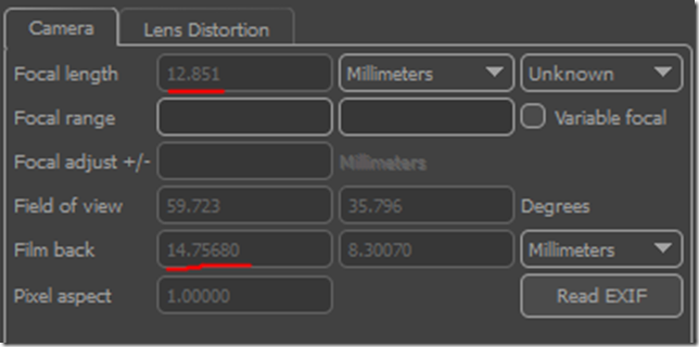
So back in Blender select the animated camera (“ImageCamera01_2”) and switch to the camera settings. Change the sensor to “Horizontal” and set the width to the film back value from PFTrack. In this case “14.75680”.
(!! Make sure your render settings are set to the same aspect ratio as your footage !!).
Then change the focal length of the camera to the value from PFTrack. In this case “12.851”.
 Verification (optional but recommended): To see if everything is correct I recommend to load the original footage as background and see if it matches correctly. Mistake with f.e. the frame rate settings happen easily. To do this select the animated camera again. With the mouse cursor in the 3D View hit “N” to show the settings of the selected object in the right bar in the 3D View.
Find “Background Image” setting and check it. Then hit the “Add Image” button.
Then select “Movie Clip” instead of “Image”. Uncheck the option “Camera Clip”. Click “Open” and navigate to the footage and click “Open Clip”.
Then click “Front” and set the Opacity to 0.500.
Now you can scrub through the time line and see if everything lines up perfectly.
Next thing of course is to create some 3D objects and place them on the table. For the final render we simply move the mesh to another layer and mix the original footage with our CGI objects in After Effects. Pay attention to things like lightning and reflection. Maybe a topic for another post ![]() . So long.
. So long.
Cheers
AndiP


