Dear readers, as promised I will now follow up with the integration of 3D objects in our tracked footage. It took a while to continue this series because my beloved father unfortunately passed away.
Today I will create some fluid simulations for our kitchen scene. Last time we tracked only the relevant part of the footage which produced a tracked camera from frame 431 to frame 618. First we will now cut down the background footage. Then we modify the tracked camera to start a frame 0.
Preparations
 Change the camera animation in Blender
In Blender change the timeline to the dope sheet and navigate to frame 430 (one before our relevant first frame). Zoom in so that you can see the key frames. Now select the menu “SELECT – Before current frame”. With the mouse over the dope sheet hit “x” to delete all key frames from 0 – 430.
Now navigate to frame 431 and select the menu “SELECT – After current frame”. Hit “g” and type “431-“ which will move all the selected key frames to frame 0. Make sure to type the minus character at the end!
Switch back to the timeline and set start and end accordingly (0/187).
 Use Adobe Media Encoder to cut down our background footage
Open Adobe Media Encoder and open preferences (STRG+,). Select Appearance/Display Format. Make sure that the frame rate is set accordingly to the frame rate of the background footage. (In my case 25 FPS).
Close preferences and drag in your footage. Choose AVI uncompressed and name the file. In my case “SHOOT27_431-618.avi”. Since Adobe Media Encoder gives us no direct way to show the current frame we are at we need to work with the time code provided. Since I recorded my footage without resetting the time code of my camera the clip starts with the time code: 11:40:51:14 which translates to 11 hours, 40 minuts, 51 seconds and 15 frames. The last number defines the frame in the case of 25FPS the value ranges from 0-24.
 Since we do want to encode starting at frame 431 we need to add this to the current starting frame 14. 431+14 = 445. Click on the time code to change it and change the last number to 445.
As soon as you hit <ENTER> to confirm the value the time code calculates correctly to: 11:41:08:20. Now set the IN-POINT by clicking on the button right next to the time code.
Similar to the start frame we navigate to the required end frame. We move the current position to the first frame and again change the number 14 to 618+14 = 632. After the current position changed we can set our OUT-POINT by clicking on the 2nd button from left next to the time code. Make sure that the output video has the same aspect ration and the same key frame rate as the original footage and encode the video.
Create 3D Model and set background footage
 Now lets create our 3D Model of a drinking glass and a plane below where we do want to simulate a wet surface later. I won’t explain the creating a simple model for a drinking glass in this tutorial. Align the 3D Models with the 3D Model you got from PF-Track. In my case this is the part of the kitchen with the window.
Switch the renderer to CYCLES in the top dropdown on blender (see image). Next we do want to load in our background footage so we can move the PF-Track model of our kitchen to another layer. With the mouse in the 3D View hit “n” to show the right toolbar. 
Scroll down to “Background Images” and select the checkbox. Then load in the background movie and set the settings like illustrated in the screen shot.
Now we will set the material for our two objects. Select the drinking glass, then the material tab and create a new material by clicking on the button “+ New Material”.
Name the material glass. Select “Glass BSDF” shader and set the color to pure white (1.0/1.0/1.0. Default is 0.8/0.8/0.8). Leave the refraction index (IOR) at 1.310. You can find a list of materials with their corresponding refraction indices here.
Since we also want to render the background footage so that it’s reflection is caught in the class we need to change the “world”-settings. In the “world-tab” open up the section “surface” and click on the “use nodes”-Button. Then click on the small button right to the color and select “Image-Texture” from the pop up menu. Select the AVI-file we created earlier, set the amount of frames, start frame and AutoRefresh. Make sure you set Vector to “Texture Coordinate | Window”.
Create the fluid simulation system
Create a fluid domain
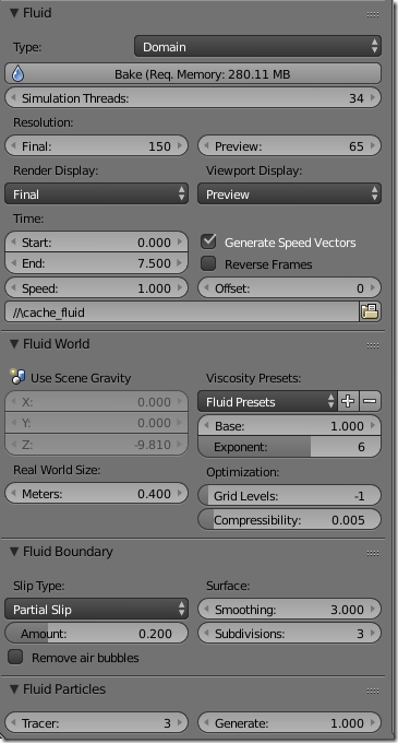
 Create a cube around the surface and the drinking glass. Switch to wireframe to see the objects within. This will be our water simulation domain. Create a material “Water” for this object. Again use the Glass BSDF shader but change the refraction index (IOR) to 1.301 and the color to pure white (1/1/1). Select the cube and switch to the tab “Physics” and click on “Fluid”. Set the type to “Domain”.
TIME: The timing of the simulation is very important. There are textboxes for Start and End. This indicates Start and End Time in SECONDS! So in our case start with 0 and end with 186 (frames) / 25 (FPS) = 7.44 (~7.4). Set the SPEED setting to 1 which indicates normal speed.
DOMAIN SIZE: To create a realistic water simulation the simulator needs to know the size the domain cube represents in the real world. Under section “Fluid World” find the setting “Real World Size”. This value indicates the longest side of the cube in meters. So a value of 0.4 represents 40 cm.
SLIP-TYPE: You can find these settings under the section “Fluid Boundary”. The slip-type determines the stickiness of the surface of the boundary (surface adhesion). You can change the surfaces Smoothing Options (0 = off, 1=Standard,…) and Subdivision (the resolution of the surface for the calculations: 1=off, 2=1 subdivide, 3=2 subdivides,…). Be careful! A high value of the resolution increases the calculation of the simulation significant.
PARTICLES: To create a more realistic simulation use particles. To be able to use particles (splash when hit boundary/obstacles) you need to set the subdivision (Boundary settings) to at least 2. Tracer allows to define how much particles already exist at the beginning od the simulation.
Create fluid obstacles
Although it is possible to use the objects we already created as obstacles in the simulation it sometimes can be more effective to create simplified versions of the objects as obstacles to reduce calculation time. To illustrate this duplicate the objects drinking glass and the “wet” surface and name them “Drinking glass obstacle” and “kitchenette surface obstacle” or similar.
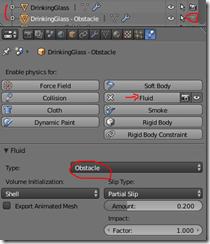
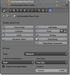
Make sure you turn rendering off for these obstacle objects. In the “Physics”-Tab select “Fluid” and choose “Obstacle” as type.

Since we have our surface set as obstacle we can modify our visible kitchenette surface and modify it to a wet ground. For that subdivide the visible plane several times and use extraction tools to shape it like a little water surface (see an example in the next section below the glass).
Create InFlow object
 Since we do want the water mysteriously appear in the middle of the air and fill the glass we need an InFlow-Object to indicate where the water will come from. Create a small sphere which you also need to hide from rendering. This sphere must reside inside the fluid domain!
 In the “Physics”-tab activate “Fluid” and set the type to “In-Flow”. We initialize the volume with the volume of the object (sphere) so we set the “Volume initialization” to “Volume”. In my case I want to have velocity along the positive x axis so I set the X velocity to 0.6.
We also do not want to poor constantly water into the glass so we enable the InFlow object only for a brief moment in time. For that we navigate to frame 0 in our time line. Activate the “Enabled”-Checkbox and right click it to insert a key frame. Move forward to frame 18. Deactivate the “Enabled”-Checkbox and set another key frame here.
Bake the fluid simulation
To bake the fluid simulation simply switch to the fluid domain object and hit the “Bake”-Button in the Physics-Tab. This will take a time. After that you will see the simulation when you scrub through the timeline and also when you render it:
Preparing render for After Effects composition
Finally we do not want to render the background footage directly but composite it later in After Effects. To do that we need to extract the background footage. Since we want to keep all the reflections we cannot simply remove the background render in the world-tab.
 For the the drinking glass and the fluid domain set the PASS INDEX to 1 (object tab). For the water surface set the PASS INDEX to 2. Switch to “Nodes”-View and and select “World” in the bottom toolbar. Use the ID-Mask nodes to isolate a alpha map for the objects with the pass index 1 and two. Then use the “Set Alpha” node to isolate the object from the rendered image. We now can take the result from ID 2 and modify it with RGB curves and make it slightly transparent by using an Alpha Over. We place the result of the isolation in the foreground (lower image input) and the the upper image to black (0/0/0) with Alpha 0. We use the factor to make the water surface transparent. In our case I set this to 0.427. We then combine the water surface and the class with the water again with an Alpha Over and take the result as final render.
Now we can finally render our animation and integrate it with the original footage in After Effects. I hope you have enjoyed this tutorial.
Cheers
AndiP


